Energy storage systems are an important part of the electricity production process. The energy storage system can establish a micro-grid to provide electricity for areas without electricity; it can adjust peak frequency and frequency to improve the operation stability of the power system; it can realize energy transfer and promote the application of new energy; the energy storage system has a major strategy for the construction of smart grids There are four kinds of meanings:
The power generation and distribution system that realizes self-control, protection and management can be connected to the external grid to form a networked microgrid, or can be operated in isolation to form an independent microgrid.
Peak and frequency regulation to improve the operation stability of the power system; shaving peaks and filling valleys to earn the economic difference of electricity prices and reduce the cost of electricity for enterprises.
The energy storage system can realize primary frequency regulation and secondary frequency regulation control, monitor load fluctuations in real-time, quickly respond to grid scheduling, and improve grid frequency stability. It can also dynamically adjust grid reactive power according to changes in grid power factor, reduce system losses, and ensure grid reliability run.
Energy storage systems are used in energy transfer and are divided into centralized and decentralized types. It can improve the limitation of photovoltaic and wind power generation, improve the economy, reduce the instantaneous power change rate, and reduce the impact of the power grid.
| Maximum working altitude | 2,000 m (>2,000m need to be derated) |
| Battery temperature control method | Industrial grade temperature control air conditioner temperature control forced air cooling |
| Inverter cooling method | Forced air cooling |
| Fire protection system (battery container) | Total submerged cabinet type heptafluoropropane automatic |
| System communication interface | RS485, Ethernet |
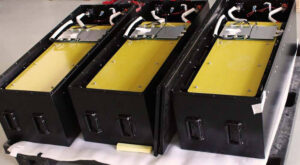
| Cell | 3.2V/86AH |
| System battery configuration | 228S32P |
| Battery rated capacity | 2007.8592KWh |
| Battery voltage range | 570-832.2V |
| Maximum DC current | 1746A |
| AC side rated power | 1MW |
| AC side rated voltage | 380V |
| Grid voltage range | ±15% |
| AC side rated current | 1520A |
| Rated grid frequency | 50Hz/60Hz |
| Output THDi | ≤3% |
| Power factor adjustable range | -1 to 1 |
| Power(KWh) | 250.9824 |
| Nominal Voltage(V) | 729.6 |
| Voltage range(V) | 570-832.2 |
| Module | 38S1P |
| High voltage box | 1 |
| Capacity(Ah) | 344 |
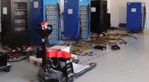
| Power(KWh) | 2007.8592 |
| Nominal Voltage(V) | 729.6 |
| Voltage range(V) | 570-832.2 |
| Battery cluster | 1S8P |
| High voltage box | 1 |
| Capacity(Ah) | 2752 |
| Working temperature (℃) | 0-50 |
| Dimensions (mm) | 12192×2438×2591 |
The system can view real-time data and historical data, and export reports according to user requirements;
Collect various state quantities of the energy storage system, including the main circuit state, fire alarm, temperature development and other information and display them;
It can also continuously record and display data statistics capabilities.
According to the difference in system demand data between the on-site monitoring layer and the general control center, the field equipment layer of the micro-grid power station can freely configure the data to be uploaded to the on-site monitoring layer and the central control center, or it can be processed and screened by the on-site monitoring layer and uploaded to the general control center;
Manual control, automatic control and remote control are available;
According to the current time period, the current load, the current on-grid electricity price, and the SOC of the energy storage battery, the system automatically control the direction of the power flow and determine the charging and discharging period of the microgrid system.
The system provides logging and exporting of fault and status events.
| DC voltage | ≤900V |
| DC maximum current | 837A |
| Number of batteries supported | 1/4/8 |
| Battery voltage range | 570~832.2V |
| Maximum DC current | 1746A |
| Rated output power | 500KW |
| Rated grid voltage | 380V |
| Grid voltage range | ±15% |
| AC rated current | 760A |
| Rated grid frequency | 50Hz/60Hz±2.5Hz |
| Output THDi | ≤3% |
| Power factor adjustable range | -1 to 1 |
| The highest efficiency of the system | 98.2% |
| Noise | 70dB |
| Communication | LAN、RS485、CAN |
The heptafluoropropane automatic fire extinguishing system is used for total submerged fire extinguishing protection. The container has partitions and can be protected by spray pipes.
The detectors are installed on the top of the container space of the energy storage station and the top of the battery cabinet. All detectors are logically ORed, that is, if one detector detects a fire, that is, the fire in the energy storage station is detected, and the fire extinguisher is automatically activated in linkage.
The container of the energy storage station shall be reserved for the installation of a pressure relief port to balance the pressure difference inside and outside the station when the gas fire extinguisher is activated.